Radio sets sometimes become misaligned. This results in a discrepancy between the received station and the frequency (or wavelength) displayed on the dial.
I am not referring here to the station names on the dial, many of which have disappeared from the LW band.
To realign (the usual term) a vintage radio, an RF signal from a generator designated by the term "heterodyne" must be sent. This RF signal is frequency adjustable between 540KHz and 1600KHz.
It is also modulated at an audible frequency (between 400 and 1000Hz). This allows the operator to adjust their radio "by ear".
If equipped with a multimeter, they can also measure the AF voltage across the loudspeaker terminals.
In normal reception mode, a real antenna detunes and dampens the input tuning circuit of radios.
That is why, during an alignment operation and to approximate real conditions,
it is necessary to insert a dummy antenna between the RF generator and the radio.
It is this "dummy" antenna that is described here.
The RF generator (heterodyne) should produce a signal modulated at 30% to be in average AM reception conditions.
Common
(Terman — Radio Engineers'HandBook)
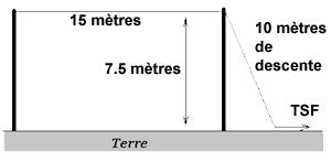
The radio set "sees" the RF generator as a long-wire type antenna of a given length and placed at a given height. It is applied for frequencies from 540KHz to 1600KHz.
RMA Model
(Terman — Radio Engineers'HandBook)
This diagram is taken from the standard test procedures used in England and described in the R. M. A. document (Wireless Proc., Vol. 12, p. 179, September, 1937).
It is intended to specify tests for evaluating the overall performance of radio receivers.
IRE Model
(USA - Source ARRL Handbook)
A dummy antenna model — circuit opposite — was defined by the IRE (USA). It simulates the impedance that would present an antenna of about 15 meters of copper wire (ø:1.5mm) stretched 7.5 meters from the ground and connected to the receiver by 10 meters of wire.

Sources and references
[1] F. E. TERMAN, "Radio Engineer's Handbook", McGraw-Hill, New York, 1943.
[2] F. LANGFORD-SMITH, "Radiotron Designer's Handbook", Radio Corporation of America - Harrison, New Jersey, 1953.


 Excerpt from Radio Engineers Handbook -- Terman (289Ko) EN